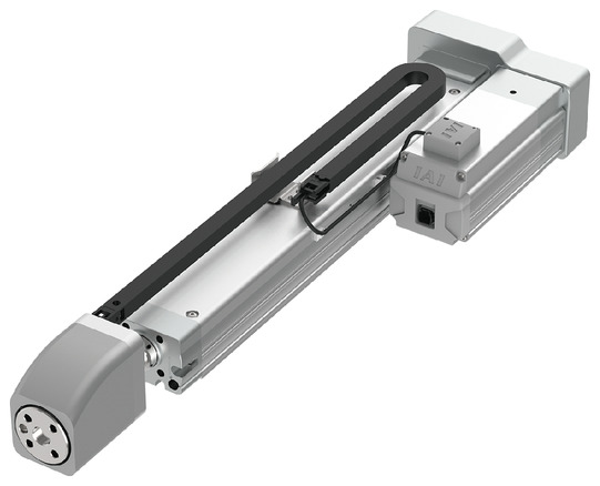
(Note) Photo above shows the motor reversing specification (Motor reversing on the left)(ML).
Main specification
| Heading | Contents | |||
|---|---|---|---|---|
| Lead | Ball screw lead (mm) | 4 | 2 | |
| Horizontal | Load capacity | Maximum load capacity (kg) (High-power enabled) | 10 | 10 |
| Maximum load capacity (kg) (High-power disabled) | 10 | 10 | ||
| Speed/ Acceleration/Deceleration | Maximum speed (mm/s) | 160 | 85 | |
| Rated acceleration/deceleration (G) | 0.3 | 0.3 | ||
| Maximum acceleration/deceleration (G) | 0.3 | 0.3 | ||
| Vertical | Load capacity | Maximum load capacity (kg) (High-power enabled) | 10 | 10 |
| Maximum load capacity (kg) (High-power disabled) | 10 | 10 | ||
| Speed/ Acceleration/Deceleration | Maximum speed (mm/s) | 160 | 85 | |
| Rated acceleration/deceleration (G) | 0.3 | 0.3 | ||
| Maximum acceleration/deceleration (G) | 0.3 | 0.3 | ||
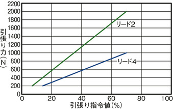
| Pressing motion | Max. pressing thrust (N) | 1000 | 2000 | |
| Min. thrust of push-motion (N) | 200 | 200 | ||
| Max. pressing speed (mm/s) | 10 | 10 | ||
| Pull-motion | Max. thrust of pull-motion (N) | 1000 | 2000 | |
| Min. thrust of pull-motion (N) | 200 | 200 | ||
| Max. speed of pull-motion (mm/s) | 10 | 10 | ||
| Brake | Brake specification | Non-excitation electromagnetic brake | ||
| Brake holding force (kg) | 10 | 10 | ||
| Stroke | Minimum stroke (mm) | 120 | 120 | |
| Maximum stroke (mm) | 320 | 320 | ||
| Stroke pitch (mm) | 50 | 50 | ||
| Heading | Contents |
|---|---|
| Drive system | Ball screw φ12mm, rolled C10 |
| Accuracy of Repeating Positioning. | ±0.02mm |
| Lost motion | 0.1mm or less |
| Rod | Φ30mm, Material: Hard alumite treated aluminum |
| Non-rotational accuracy of rod | ±0.1 degree (Note 6) |
| Load cell rated capacity | 2000N |
| Repetitive load accuracy (Note 7) | ±1.0% F.S. (Note 8) |
| Ambient operating temperature and humidity | 0 - 40℃, 5 - 85%RH or less (no condensation) |
| Protection grade | IP20 |
| Vibration resistant/Shock resistant | 4.9m/s2 |
| Compatible to overseas standards | CE mark, RoHS compliant |
| Motor type | Pulse motor |
| Encoder type | Battery-less absolute |
| Encoder pulse No. | 8192 pulse/rev |
| Delivery | Written in [Reference for delivery] section of the homepage |
(Note 6) This is the displacement angle (initial value guideline) of the rod tip when static allowable torque (1N m) is applied to the rod tip when it is fully retracted into the main body.
(Note 7) This value represents the variation in load caused by repeated operations as a ratio to the rated capacity of the load cell.
(Note 8) F.S.: Full Scale Maximum measurable value.
Stroke and maximum speed
(Measured in mm/s)
| Lead (mm) | Pushing force Pulling force | High power setting | Stroke (mm) | ||||
|---|---|---|---|---|---|---|---|
| 120 | 170 | 220 | 270 | 320 | |||
| 4 | 1000N | Valid | 160 | ||||
| Invalid | 115 | ||||||
| 2 | 2000N | Valid | 85 | ||||
| Invalid | 60 | ||||||
Correlation diagram between pushing force and pushing command value
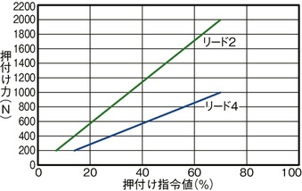
Correlation diagram between pulling force and pulling command value
Load capacity by speed and acceleration table
High-power setting enabled Base unit of load capacity is in kilogram (kg).
| Orientation | Horizontal | Vertical |
|---|---|---|
| Speed (mm/s) | Acceleration (G) | |
| 0.3 | 0.3 | |
| 0 | 10 | 10 |
| 35 | 10 | 10 |
| 70 | 10 | 10 |
| 115 | 10 | 10 |
| 160 | 10 | 10 |
| Orientation | Horizontal | Vertical |
|---|---|---|
| Speed (mm/s) | Acceleration (G) | |
| 0.3 | 0.3 | |
| 0 | 10 | 10 |
| 35 | 10 | 10 |
| 70 | 10 | 10 |
| 85 | 10 | 10 |
High-power setting disabled Base unit of load capacity is in kilogram (kg).
| Orientation | Horizontal | Vertical |
|---|---|---|
| Speed (mm/s) | Acceleration (G) | |
| 0.3 | 0.3 | |
| 0 | 10 | 10 |
| 35 | 10 | 10 |
| 70 | 10 | 10 |
| 115 | 10 | 10 |
| Orientation | Horizontal | Vertical |
|---|---|---|
| Speed (mm/s) | Acceleration (G) | |
| 0.3 | 0.3 | |
| 0 | 10 | 10 |
| 35 | 10 | 10 |
| 60 | 10 | 10 |
Adaptive controller
The actuators introduced in this page are controllable using the controllers shown below. Please select their type based on intended usage.
| Name | Appearance | Max. connectable axis No. | Power source voltage | Control method | Maximum positioning points | ||||||||||||||
|---|---|---|---|---|---|---|---|---|---|---|---|---|---|---|---|---|---|---|---|
| Positioner | Pulse train | Program | Network *Select | ||||||||||||||||
| DV | CC | CIE | PR | CN | ML | ML3 | EC | EP | PRT | SSN | ECM | ||||||||
| PCON-CBP/CGBP |  | 1 | DC24V | ● *Selectable | - | - | ● | ● | ● | ● | ● | ● | - | ● | ● | ● | - | - | 512 (768 for network specification) |
(Note) For network abbreviations such as DV and CC, please refer to page 8-15.
Oversea specification
Important notes on selection
| (1) There are no restrictions on the continuous pressing time and the continuous pulling time. (2) It can operate continuously when the duty ratio is 100%. (3) An extra care must be taken depending on how the main unit is installed. Refer to page 6-112 for further details. (4) Requires extra care required depending on the mounting posture. Refer to page 1-307 for further details. (5) Please refer to page 6-112 for the load cell. |
Dimension drawing
ST: Stroke
M.E.: Mechanical end
S.E.: Stroke end
(Note) When returning to the home position, the rod moves to M.E. Please be careful of interference with surrounding objects.
(Note) The figure below shows a motor with left-reversing specification (ML).
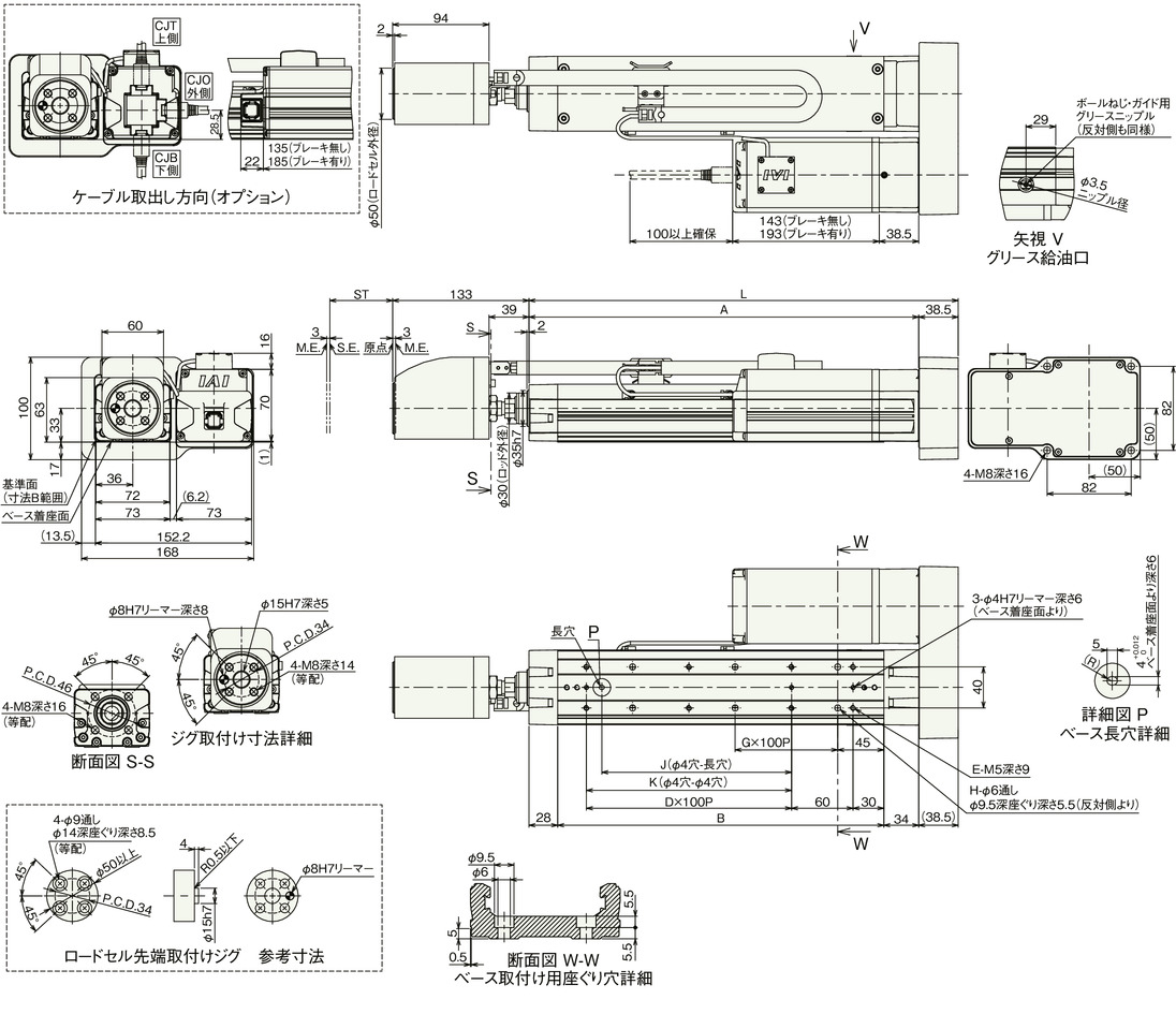
Dimension by stroke length
| Stroke | 120 | 170 | 220 | 270 | 320 |
|---|---|---|---|---|---|
| L | 318.5 | 368.5 | 418.5 | 468.5 | 518.5 |
| A | 280 | 330 | 380 | 430 | 480 |
| B | 218 | 268 | 318 | 368 | 418 |
| D | 1 | 1 | 2 | 2 | 3 |
| E | 6 | 6 | 8 | 8 | 10 |
| G | 1 | 2 | 2 | 3 | 3 |
| H | 4 | 6 | 6 | 8 | 8 |
| J | 85 | 85 | 185 | 185 | 285 |
| K | 100 | 100 | 200 | 200 | 300 |
Mass by stroke length
| Stroke | 120 | 170 | 220 | 270 | 320 | |
|---|---|---|---|---|---|---|
| Mass (kg) | Without brake | 6.0 | 6.3 | 6.6 | 6.9 | 7.2 |
| With brake | 6.6 | 6.9 | 7.2 | 7.5 | 7.8 | |


